About 3D

Organisation:Copyright (C) 2021-2024 Olivier Boudeville
Contact:about (dash) howtos (at) esperide (dot) com
Creation date:Saturday, November 20, 2021
Lastly updated:Sunday, February 4, 2024

As usual, these information pertain to a GNU/Linux perspective.

Cross-Platform Game Engines

The big three are Godot, Unreal Engine and Unity3D [1].

[1]Others could be considered, like Cocos Creator, an open-source engine using TypeScript and WebGL.

Godot

Godot is our personal favorite engine, notably because it is free software (released under the very permissive MIT license).

See its official website and its asset library.

Godot (version 3.4.1) will not be able to load FBX files that reference formats like PSD or TIF and/or of older versions (e.g. FBX 6.1). See for that our section regarding format conversions.

Installation

On Arch Linux, one may simply use pacman -Sy godot.

Or just, for maximum control, one may instead directly download the GNU/Linux version from the Godot official website.

If planning to be able to develop in C# in addition to GDScript (refer to our Scripting Language section), prefer the .NET version (as opposed to the Standard one), i.e. the ".NET (x86_64)" version - provided that the support for .NET is already secured, either based on the Microsoft .NET SDK or, possibly better, on the Mono SDK.

The installation procedure that we prefer can be done automatically thanks to our install-godot.sh script.

Use

Scripting Language

Users of the Godot API may develop notably in GDScript (extension: *.gd) and/or in C# (extension: *.cs) and/or in C++.

See this comparison - knowing that languages can be mixed and matched.

We prefer using C# to GDScript or C++, as:

  • C# is statically typed (GDScript is dynamically typed, with implicit casts)
  • C# is widely-used / general-purpose (and Unity supports it as well), as opposed to GDScript
  • C# is C++-inspired (yet offers a safer model, notably in terms of life-cycle management), whereas GDScript is Python-inspired [2]; so for example C# does not rely on indentation to define clauses
[2]With additionally quite many differences. For example, with GDScript, variables are typed, like in var my_msg : String = 'Hello!'. So my_msg = 7 is to result in a (runtime) error. Python lists are Godot arrays. None is null. A switch-like operator (match) exists, etc.

Development Hints

  • all scripts are classes, which are by default anonymous

Important Paths

A configuration tree lies in .config/godot, a cache tree in ~/.cache/godot.

Logs

Godot logs are stored per-project; e.g. ~/.local/share/godot/app_userdata/my-test-project/logs/godot.log; past log files are kept once timestamped. They tend not to have interesting content.

Assets

The official Godot Asset Library, whose assets are at least mostly available through the rather permissive MIT licence, coexists with (probably too many) unofficial ones, like Godot A.L. (AGPLv3 license), Godot Asset Store, GodotAssets, etc.

For obvious reasons, many of the current open source assets are of a significantly lower quality than their non-Godot commercial counterparts. We believe than, until Godot-related assets progress (either as open-source or commercial ones), as soon as a game is a bit ambitious, relying on the asset stores of the other engines (see Engine-related Assets) and/or on asset providers is a better option.

Unreal Engine

Another contender is the Unreal Engine, a C++ game engine developed by Epic Games; we have not used it yet.

The Unreal Engine 5 brings new features that may be of interest, including a fully dynamic global illumination and reflection system (Lumen, not requiring baked lightmaps anymore), a virtualized geometry system (Nanite, simplifying detailed geometries on the fly) and a quality 2D/3D asset library (the Quixel Megascans library, obtained from real-world scans).

Unreal does not offer a scripting language anymore, user developments have to be done in C++ (beyond Blueprints Visual Scripting).

Its licence is meant to induce costs only when making large-enough profits; more precisely, a 5% royalty is due only if you are distributing an off-the-shelf product that incorporates Unreal Engine code (such as a game) and the lifetime gross revenue from that product exceeds $1 million USD (the first $1 million remaining royalty-exempt); in case of large success, it may be a costlier licence than Unity.

With an Unreal user account, the sources of the engine (in its latest stable version, 5) can be examined on Github (so it is open source - yet not free software).

See its official website.

Unreal Assets

Purchased assets from the Unreal marketplace may be used in one's own shipped products (source) and apparently at least usually no restrictive terms apply.

Assets not created by Epic Games can be used in other engines unless otherwise specified (source; see also this thread).

Note that parts of the content of assets will be Unreal-specific (*.uasset, *.umap, etc.), like scripts. Yet technically many can be adapted to other engines (see for example Exporting from Unreal Engine to Godot).

Unity3D

Unity is most probably still the most popular cross-platform game engine, despite recent controversies.

Regarding the licensing of the engine, various plans apply (warning: they may have changed since this writing), depending notably on whether one subscribes as an individual or a team, and on one's profile, revenue and funding; the general idea is not taking royalties, but flat, per seat yearly fees increasing with the organisation "size" (typically in the $400-$1800 range, per seat).

See its official website and its asset store.

Unity may be installed at least in order to access its asset store, knowing that apparently an asset purchased in this store may be used with any game engine of choice. Indeed, for the standard licence, it is stipulated in the EULA legal terms that:

Licensor grants to the END-USER a non-exclusive, worldwide, and perpetual license to the Asset to integrate Assets only as incorporated and embedded components of electronic games and interactive media and distribute such electronic game and interactive media.

So, in legal terms, an asset could be bought in the Unity Asset Store and used in Godot, for example - provided that its content can be used there technically without too much effort/constraints (this may happen due to prefabs, specific animations, materials or shaders, conventions in use, etc.).

Installation

Unity shall now be obtained thanks to the Unity Hub.

On Arch Linux it is available through the AUR, as an AppImage; one may thus use: yay -Sy unityhub.

Then, when running (as a non-privileged user) unityhub, a Unity account will be needed, then a licence, then a Unity release will have to be added in order to have it downloaded and installed for good, covering the selected target platforms (e.g. GNU/Linux and Windows "Build Supports").

We rely here on the Unity version 2021.2.7f1.

Additional information: Unity3D on Arch.

Configuration

Configuring Unity so that its interface (mouse, keyboard bindings) behave like, for example, the one of Blender, is not natively supported.

Running Unity

Just execute unityhub, which requires signing up and activating a licence.

Troubleshooting

The log files are stored in ~/.config/unity3d:

  • Unity Editor: Editor.log (the most interesting one)
  • Unity Package Manager: upm.log
  • Unity Licensing client: Unity.Licensing.Client.log

If the editor is stuck (e.g. when importing an asset), one may use as a last resort kill-unity3d.sh.

In term of persistent state, beyond the project trees themselves, there are:

  • ~/.config/UnityHub/ and ~/.local/share/UnityHub/
  • ~/.config/unity3d/ and ~/.local/share/unity3d/

(nothing in ~/.cache apparently)

Unity Assets

Once ordered through the Unity Asset Store, assets can be downloaded through the Window -> Package Manager menu, by replacing, in the top Packages drop-down, the In Project entry by the My Assets one. After having selected an asset, use the Download button at the bottom-right of the screen.

Then, to gain access to such downloaded assets, of course the simplest approach is to use the Unity editor; this is done by creating a project (e.g. MyProject), selecting the aforementioned menu option (just above), then clicking on Import and selecting the relevant content that will end up in clear form in your project, i.e. in the filesystem of the operating system with their actual name and content, for example in MyProject/Assets/CorrespondingAssetProvider/AssetName. Unfortunately we experienced reproducible freezes when importing some resources.

Yet such Unity packages, once downloaded (whether or not they have been imported in projects afterwards) are just files that are stored typically in the ~/.local/share/unity3d/Asset Store-5.x directory and whose extension is .unitypackage.

Such files are actually .tar.gz archives, and thus their content can be listed thanks to:

$ tar tvzf Foobar.unitypackage

Inside such archives, each individual package resource is located in a directory whose name is probably akin to the checksum of this resource (e.g. 167e85f3d750117459ff6199b79166fd) [3]; such directory generally contains at least 3 files:

  • asset: the resource itself, renamed to that unique checksum name, yet containing its exact original content (e.g. the one of a Targa image)
  • asset.meta: the metadata about that asset (file format, identifier, timestamp, type-specific settings, etc.), as an ASCII, YAML-like, text
  • pathname: the path of that asset in the package "virtual" tree (e.g. Assets/Foo/Textures/baz.tga)

When applicable, a preview.png file may also exist.

[3]Yet no checksum tool among md5sum, sha1sum, sha256sum, sha512sum, shasum, sha224sum, sha384sum seems to correspond; it must a be a different, possibly custom, checksum.

Some types of content are Unity-specific and thus may not transpose (at least directly) to another game engine. This is the case for example for materials or prefabs (whose file format is relatively simple, based on YAML 1.1).

Tools like AssetStudio (probably Windows-only) strive to automate most of the process of exploring, extracting and exporting Unity assets.

Meshes are typically in the FBX (proprietary) file format, that can nevertheless be imported in Blender and converted to other file formats (e.g. glTF 2.0); see blender import and blender convert for that.

3D Data

File Formats

They are designed to store 3D content (scenes, nodes, vertices, normals, meshes, textures, materials, animations, skins, cameras, lights, etc.).

glTF

We prefer relying on the open, well-specified, modern glTF 2.0 format in order to perform import/export operations.

It comes in two forms:

  • either as *.gltf when JSON-based, possibly embedding the actual data (vertices, normals, textures, etc.) as ASCII base64-encoded content, or referencing external files
  • or as *.glb when binary; this is the most compact form, and the one that we recommend for actual releases

See also the glTF 2.0 quick reference guide, the related section of Godot and this standard viewer of predefined glTF samples.

This (generic) online glTF viewer proved lightweight and convenient, notably because it displays errors, warnings and information regarding the glTF data that it decodes.

Collada

The second best choice that we see is Collada (*.dae files), an XML-based counterpart (open as well, yet older and with less validating facilities) to glTF.

FBX, OBJ, etc.

Often, assets can be found as FBX of OBJ files and thus may have to be converted (typically to glTF), which is never a riskless task. FBX comes in two flavours: text-based (ASCII) or binary; see this retro-specification for more information.

In General

Refer to blender import in order to handle the most common 3D file formats, and the next section about conversions.

The file command is able to report the version of at least some formats; for example:

# Means FBX 7.3:
$ file foobar.fbx
foobar.fbx: Kaydara FBX model, version 7300

Too often, some tool will not be able to load a file and will fail to properly report why. When suspecting that a binary file (e.g. a FBX one) references external content either missing or in an unsupported format (e.g. PSD or TIFF?), one may peek at their content without any dedicated tool, directly from a terminal, like in:

$ strings my_asset.fbx | sort | uniq | grep '\.'

This should list, among other elements, the paths that such a binary file is embedding.

Conversions

Due to the larger number of 3D file formats and the role of commercial software, interoperability regarding 3D content is poor and depends on many versions (of tools and formats).

Workaround #1: Using Autodesk FBX Converter

The simpler approach seems to download the (free) Autodesk FBX Converter and to use wine to run it on GNU/Linux. Just install then this converter with: wine fbx20133_converter_win_x64.exe.

A convenient alias (based on default settings, typically to be put in one's ~/.bashrc) can then be defined to run it:

$ alias fbx-converter-ui="$HOME/.wine/drive_c/Program\ Files/Autodesk/FBX/FBX\ Converter/2013.3/FBXConverterUI.exe 2>/dev/null &"

Conversions may take place from, for example, FBX 6.1 (also: 3DS, DAE, DXF, OBJ) to a FBX version in: 2006, 2009, 2010, 2011, 2013 (i.e. 7.3 - of course the most interesting one here), but also DXF, OBJ and Collada, with various settings (embedded media, binary/ASCII mode, etc.).

An even better option is to use directly the command-line tool bin/FbxConverter.exe, which the previous user interface actually executes. Use its /? option to get help, with interesting information.

For example, to update a file in a presumably older FBX into a 7.3 one (that Blender can import):

$ cd ~/.wine/drive_c/Program\ Files/Autodesk/FBX/FBX\ Converter/2013.3/bin
$ FbxConverter.exe My-legacy.FBX newer.fbx /v /sffFBX /dffFBX /e /f201300

We devised the update-fbx.sh script to automate such an in-place FBX update.

Unfortunately, at least on one FBX sample taken from a Unity package, if the mesh could be imported in Blender, textures and materials were not (having checked Embed media in the converter or not).

Workaround #2: Relying on Unity

Here the principle is to import a content in Unity (the same could probably be done with Godot), and to export it from there.

Unity does not allow to export for example FBX natively, however a package for that is provided. It shall be installed first, once per project.

One shall select in the menu Window -> Package Manager, ensure that the entry Packages: points to Unity Registry, and search for FBX Exporter, then install it (bottom right button).

Afterwards, in the GameObject menu, an Export to FBX option will be available. Select the Binary export format (not ASCII) if wanting to be compliant with Blender.

Examples of 3D Content

Here are a few samples of 3D content (useful for testing):

Asset Providers

Usually, for one's creation, much multimedia artwork has to be secured: typically graphical assets (e.g. 2D/3D geometries, animations, textures) and/or audio ones (e.g. music, sounds, speech syntheses, special effects).

Instead of creating such content by oneself (not enough time/interest/skill?), it may be more relevant to rely on specialised third-parties.

Hiring a professional or a freelance is then an option. This is of course relatively expensive, involves more efforts (to define requirements and review the results), longer, but it is supposed to provide exactly the artwork that one would like.

Another option is to rely on specialised third-party providers who sell non-exclusive licences for the content that they offer.

These providers can be either direct content producers (companies with staffs of modellers), or asset aggregators (marketplaces that federate the offers of many producers of any size) that are often created in link to a given multimedia engine. An interesting point is that assets purchased in these stores generally can be used in any technical context, hence are not meant to be bound to the corresponding engine.

Nowadays, much content is available, in terms of theme/setting (e.g. Medieval, Science-Fiction), of nature (e.g. characters, environments, vehicles), etc. and the overall quality/price ratio seems rather good.

The main advantages of these marketplaces is that:

  • they favor the competition between content providers: the clients can easily compare assets and share their opinion about them
  • they generalised simple, standard, unobtrusive licensing terms; e.g. royalty free, allowing content to be used as they are or in a modified form, not limited by types of usage, number of distributed copies, duration of use, number of countries addressed, etc.; the general rule is that much freedom is left to the asset purchasers provided that they use such assets for their own projects (rather than for example selling the artwork as they are)

The main content aggregators that we spotted are (roughly by decreasing order of interest, based on our limited experience):

  • the Unity Asset Store, already discussed in the Unity Assets section; websites like this one allow to track the significant discounts that are regularly made on assets
  • the UE Marketplace, i.e. the store associated to the Unreal Engine; in terms of licensing and uses (see also this section):
    • this article states that When customers purchase Marketplace products, they get a non-exclusive, worldwide, perpetual license to download, use, copy, post, modify, promote, license, sell, publicly perform, publicly display, digitally perform, distribute, or transmit your product’s content for personal, promotional, and/or commercial purposes. Distribution of products via the Marketplace is not a sale of the content but the granting of digital rights to the customer.
    • this one states that Any Marketplace products that have not been created by Epic Games can be used in other engines unless otherwise specified.
    • this one states that All products sold on the Marketplace are licensed to the customer (who may be either an individual or company) for the lifetime right to use the content in developing an unlimited number of products and in shipping those products. The customer is also licensed to make the content available to employees and contractors for the sole purpose of contributing to products controlled by the customer.
  • itch.io
  • Turbosquid
  • Free3D
  • CGtrader
  • ArtStation
  • Sketchfab
  • 3DRT
  • Reallusion
  • Arteria3D
  • the GameDev Market (GDM)
  • the Game Creator Store

Many asset providers organise interesting discount offers (at least -50% on a selection of assets, sometimes even more for limited quantities) for the Black Friday (hence end of November) or for Christmas (hence mid-December till the first days of January).

Modelling Software

Blender

Blender is a very powerful free software 3D toolset.

Blender (version 3.0.0) can import FBX files of version at least 7.1 ("7100"). See for that our section regarding format conversions.

We recommend the use of our Blender shell scripts in order to:

  • import conveniently various file formats in Blender, with blender-import.sh
  • convert directly on the command-line various file formats (still thanks to a non-interactive Blender), with blender-convert.sh

Wings3D

Wings3D is a nice, Erlang-based, free software, advanced subdivision modeler [4], available for GNU/Linux, Windows and Mac OS X. Wings3D relies on OpenGL.

[4]As opposed to renderer; yet Wings3D integrates an OpenCL renderer as well, deriving from LuxCoreRender, an open-source Physically Based Renderer (it simulates the flow of light according to physical equations, thus producing realistic images of photographic quality).

It can be installed on Arch Linux, from the AUR, as wings3d; one can also rely on our Wings3D shell scripts in order to install and/or execute it.

We prefer using the Blender-like camera navigation conventions, which can be set in Wings3D by selecting Edit -> Preferences -> Camera -> Camera Mode to Blender.

See also:

Other Tools

Draco

Draco is an open-source library for compressing and decompressing 3D geometric meshes and point clouds.

It is intended to improve the storage and transmission of 3D graphics; it can be used with glTF, with Blender, with Compressonator, or separately.

A draco AUR package exists, and results notably in creating the /usr/lib/libdraco.so shared library file.

Even once this package is installed, when Blender exports a mesh, a message like the following is displayed:

'/usr/bin/3.0/python/lib/python3.10/site-packages/libextern_draco.so' does
not exist, draco mesh compression not available, please add it or create
environment variable BLENDER_EXTERN_DRACO_LIBRARY_PATH pointing to the folder

Setting the environment prior to running Blender is necessary (and done by our blender-*.sh scripts):

$ export BLENDER_EXTERN_DRACO_LIBRARY_PATH=/usr/lib

but not sufficient, as the built library does not bear the expected name.

So, as root, one shall fix that once for all:

$ cd /usr/lib
$ ln -s libdraco.so libextern_draco.so

Then the log message will become:

'/usr/lib/libextern_draco.so' exists, draco mesh compression is available

The Compressonator

The Compressonator is an AMD tool (as a GUI, a command-line executable and a SDK) designed to compress textures (e.g. in DXT1, DXT3 or DXT5 formats; typically resulting in a .dds extension) and to generate mipmaps ahead of time, so that it does not have to be done at runtime.

F3D

f3d (installable from the AUR) is a fast and minimalist VTK-based 3D viewer.

Such a viewer is especially interesting to investigate whether a tool failed to properly export a content or whether it is the next tool that actually failed to properly import, and to gain another chance of accessing to relevant error messages.

Mikktspace

This tool (official website), created by Morten S. Mikkelsen, is a de facto (free) standard in terms of normal map baker: it generates Tangent Space Normal Maps (tangents), and helps ensuring consistency between 3D applications (such as Blender).

These fields of normals may be seen as an encoding - explaining why conventions like the ones enforced by this tool (which became an implementation standard) help performing a suitable, robust reciprocal decoding.

Mixamo

Mixamo is a website that allows to download and use for free a large number of rather high-quality 3D characters (about 110 of them; all being textured and rigged) and animations (about 2500 of them; full-body character animations, captured from professional motion actors), which can be arbitrarily mixed and matched.

This website allows also to rig one's (humanoid) character (see Upload character).

The licence attached to Mixamo is rather permissive; notably:

You can use both characters and animations royalty free for personal, commercial, and non-profit projects including:
   Incorporate characters into illustrations and graphic art.
   3D print characters.
   Create films.
   Create video games.

OpenGL Corner

Conventions

Refer to our Mini OpenGL Glossary for most of the terms used in these sections.

Code snippets will correspond to the OpenGL/GLU APIs as they are exposed in Erlang, in the gl and glu modules respectively.

These translate easily for instance in the vanilla C GL/GLU implementations. As an example, gl:ortho/6 (6 designating here the arity of that function, i.e. the number of the arguments that it takes) corresponds to its C counterpart, glOrtho.

The reference pages for OpenGL (in version 4.x) can be browsed here.

Note that initially the information in this page related to older versions of OpenGL (1.1, 2.1, etc.; see history) that relied on a fixed pipeline (no shader support) - whereas, starting from OpenGL 3.0, many of the corresponding features were marked as deprecated, and actually removed as a whole in 3.1. However, thanks to the compatibility context (whose support is not mandatory - but that all major implementations of OpenGL provide), these features can still be used.

Yet nowadays relying on at least the OpenGL 3 core context (not using the compatibility context) would be preferable (source: this thread). Still better options would be to rely on OpenGL 4 Core or OpenGL ES 2+, or libraries on top of Vulkan, like wgpu. Specific libraries also exist for rendering for the web and for mobile, like WebGPU.

As of 2023, the current OpenGL version is 4.6; we will try to stick to the latest ones (4.x) only (e.g. skipping intermediate changes in 3.2); even though in this document reminiscences of older OpenGL versions remain, the current minimum that we target is the Core Profile of OpenGL 3.3, which is "modern OpenGL" and introduced most features that still apply; it will halt on error if any deprecated functionality is used.

For more general-purpose computations (as opposed to rendering operations) to be offset to a GPU/GPGU, one may rely on OpenCL instead.

The mentioned tests will be Ceylan-Myriad ones, typically located here.

Basics

  • OpenGL is a software interface to graphics hardware, i.e. the specification of an API (of around 150 functions in its older version 1.1), developed and maintained by the Khronos Group
  • a video card will run an implementation of that specification, generally developed by the manufacturer of that card; a good rule of thumb is to always update one's video card drivers to their latest stable version, as OpenGL implementations are constantly improved (bug-fixing) and updated (with regard to newer OpenGL versions)
  • OpenGL concentrates on hardware-independent 2D/3D rendering; no commands for performing window-related tasks or obtaining user input are included; for example frame buffer configuration is done outside of OpenGL, in conjunction with the windowing system
  • OpenGL offers only low-level primitives organised through a pipeline in which vertices are assembled into primitives, then to fragments, and finally to pixels in the frame buffer; as such, OpenGL is a building-block for higher-level engines (e.g. like Godot)
  • OpenGL is a procedural (function-based, not object-oriented) state machine comprising a larger number of variables defined within a given OpenGL state (named an OpenGL context; comprising vertex coordinates, textures, frame buffer, etc.); said otherwise, all OpenGL state variables behave like "global" variables, more precisely they are actually relative to an OpenGL context that is often implicit; when a parameter is set, it applies and lasts as long as it is not modified (if still using the same OpenGL context); the effect of an OpenGL command may vary depending on whether certain modes are enabled (i.e. whether some state variables are set to a given value)
  • so the currently processed element (e.g. a vertex) inherits (implicitly) the current settings of the context (e.g. color, normal, texture coordinate, etc.); this is the only reasonable mode of operation, knowing that a host of parameters apply whenever performing a rendering operation (specifying all these parameters would not be a realistic option); as a result, any specific parameter shall be set first (prior to triggering such an operation), and is to last afterwards (being "implicitly inherited"), until possibly being reassigned in some later point in time
  • OpenGL respects a client/server execution model: an application (a specific client, running on a CPU) issues commands to a rendering server (on the same host or not - see GLX; generally the server can be seen as running on a local graphic card), that executes them sequentially and in-order; as such, most of the calls performed by user programs are asynchronous: they are triggered by the (client) program through OpenGL, and return almost immediately, whereas they have not been executed (by the server) yet: they have just be queued; indeed OpenGL implementations are almost always pipelined, so the rendering must be thought as primarily taking place in a background process; additional facilities like Display Lists allow to pipeline operations (as opposed to the default immediate mode), which are accumulated for processing at a later time, as fast as the graphic card can then process them
  • state variables are mostly server-side, yet some of them are client-side; in both cases, they can be gathered in attribute groups, which can be pushed on, and popped from, their respective server or client attribute stacks
  • OpenGL manages two types of data, handled by mostly different paths of its rendering pipeline, yet that are ultimately integrated in the framebuffer through fragment-yielding rasterization:
    • geometric data (vertices, lines, and polygons)
    • pixel data (pixels, images, and bitmaps)
  • vertices and normals are transformed by the model-view and projection matrices (that can be each set and transformed on a stack of their own), before being used to produce an image in the frame buffer; as for texture coordinates, they are transformed by the texture matrix
  • textures may reside in the main, general-purpose, client, CPU-side memory (large, but slow to access for the rendering) and/or in any auxiliary, dedicated, server-side GPU memory (more constrained, hence prioritized thanks to texture objects; and, rendering-wise, of significantly higher performance)
  • OpenGL has to apply varied kinds of transformations - "linear" (e.g. rotation, scaling) or not (e.g. translation, perspective) - to geometries, for example in order to perform referential changes or rendering; each of these transformations can be represented as a 4x4 homogeneous matrix, with floating-point (homogeneous) coordinates [5]; a series of transformations can then simply be represented as a single of such matrices, corresponding to the product of the involved transformation matrices
[5]

So a 3D point is specified based on 4 coordinates: \(P = \begin{pmatrix} x \\ y \\ z \\ w \end{pmatrix}\), with w being usually equal to 1.0 (otherwise the point can be normalised by dividing each of its coordinates by w, provided of course that w is not null - otherwise these coordinates do not specify a point but a direction).

Thus summing (like vectors) two 4D points actually returns their mid-point (center of segment), as w will be normalised: \(P1 + P2 = \begin{pmatrix} x1 \\ y1 \\ z1 \\ 1.0 \end{pmatrix} + \begin{pmatrix} x2 \\ y2 \\ z2 \\ 1.0 \end{pmatrix} = \begin{pmatrix} x1+x2 \\ y1+y1 \\ z1+z2 \\ 2.0 \end{pmatrix} = \begin{pmatrix} (x1+x2)/2.0 \\ (y1+y2)/2.0 \\ (z1+z2)/2.0 \\ 1.0 \end{pmatrix}\)

  • while this will not change anything regarding the actual OpenGL library and the computations that it performs, the conventions adopted by the OpenGL documentation regarding matrices are the following ones:

    • their in-memory representation is column-major order (even if it is unusual, at least in C; this corresponds to Fortran-like conventions), meaning that it enumerates their coordinates first per column rather than per row (and for them a vector is a row of coordinates), whereas tools following the row-major counterpart order, including Myriad, do the opposite (and for them vectors are columns of coordinates); more clearly, a matrix like \(M = \begin{bmatrix} a11 & a12 & ... & a1n \\ a21 & a22 & ... & a2n \\ ... & ... & ... & ... \\ am1 & am2 & ... & amn \\ \end{bmatrix}\)
      • will be stored with row-major conventions (e.g. Myriad) as: a11, a12, ... a1n, a21, a22, ... a2n, am1, am2, ... amn (or, more precisely, as [[a11, a12, ... a1n], [a21, a22, ... a2n], ..., [am1, am2, ... amn]])
      • whereas, with the conventions discussed, OpenGL will expect it to be stored in-memory in this order: a11, a21, ..., am1, a21, a22, ..., am2, ..., a1n, a2n, ..., amn, i.e. as the transpose of the previous matrix
    • these OpenGL storage conventions do not tell how matrices are to be multiplied (knowing of course that the matrix product is not commutative); if following the aforementioned OpenGL documentation conventions, one should consider that OpenGL relies on the usual multiplication order, that is post-multiplication, i.e. multiplication on the right; this means that, if applying on a given matrix \(M\) a transformation \(O\) (e.g. rotation, translation, scaling, etc.) represented by a matrix \(M_O\), the resulting matrix will be \(M' = M.M_O\) (and not \(M' = M_O.M\)); a series of operations \(O_1\), then \(O_2\), ..., then \(O_n\) will therefore correspond to a matrix \(M' = M_{O1}.M_{O2}.[...].M_{On}\); applying a vector \(\vec{V}\) to a matrix \(M\) will result in \(\vec{V'} = M.\vec{V}\)
    • so when an OpenGL program performs calls implementing first a rotation (r), then a scaling (s) and finally a translation (t):
    glRotatef(90, 0, 1, 0);
    glScalef(1.0, 1.1, 1.0);
    glTranslatef(5,10,5);
    

    the current matrix \(M\) ends up being multiplied (on the right) by \(M' = M_r.M_s.M_t\); when applied to a vector \(\vec{V}\), still multiplying on the right results in \(\vec{V'} = M.\vec{V} = M.M_r.M_s.M_t.\vec{V}'\); so the input vector \(\vec{V}\) is first translated, then the result is scaled, then rotated, then transformed by the previous matrix \(M\); as a result: operations happen in the opposite order of their specification as calls; said differently: one shall specify the calls corresponding to one's target series of transformations backwards

    • considering that the OpenGL storage is done in a surprising column-major order was actually a trick so that OpenGL could rely on the (modern, math-originating) vector-as-column convention while being still compliant with its GL ancestor - which relied on the (now unusual) vector-as-row convention and on pre-multiplication (where we would have \(M' = M_O.M\)); indeed, knowing that, when transposing matrices, \((A.B)^\top = B^\top.A^\top\), one may consider that OpenGL actually always operates on transpose elements, and thus that: (1) matrices are actually specified in row-order and (2) they are multiplied on the left (e.g. \(M' = M_t.M_s.M_r.M\)); note that switching convention does not affect at all the computations, and that the same operations are always performed in reverse call order
  • OpenGL can operate on three mutually exclusive modes:
    • rendering: is the default, most common mode, discussed here
    • feedback: allows to capture the primitives generated by the vertex processing, i.e. to establish the primitives that would be displayed after the transformation and clipping steps; often used in order to resubmit this data multiple times
    • selection: determines which primitives would be drawn into some region of a window (like in feedback mode), yet based on stacks of only user-specified "names" (so that the actual data of the corresponding primitives is not returned, just their name identifier); a special case of selection is picking, allowing to determine what are the primitives rendered at a given point of the viewport (typically the onscreen position of the mouse cursor, to enable corresponding interactions)

Steps for OpenGL Rendering

The usual analogy to describe them is the process of producing a photography:

  1. a set of elements (3D objects) can be placed (in terms of position and orientation) as wanted in order to compose one's scene of interest (modelling transformations, based on world coordinates)
  2. the photographer may similarly place as wanted at least one camera (viewing transformations, based on camera coordinates)
  3. the settings of the camera can be adjusted, for example regarding its lens / zoom factor (projection transformations, based on window coordinates)
  4. the snapshots that it takes can be further adapted before being printed, for example in terms of scaling (viewport transformations, based on screen coordinates)

One can see that the first two steps are reciprocal; for example, moving all objects in a direction or moving the camera in the opposite direction is basically the same operation. These two operations, being the two sides of the same coin, can thus be managed by a single matrix, the model-view one.

Finally, as mentioned in the section about storage conventions, in OpenGL, operations are to be defined in reverse order. If naming \(M_s\) the matrix implementing a given step S, the previous process would be implemented by an overall matrix, based on the previous bullet numbers: \(M = M_4.M_3.M_2.M_1\), so that applying a vector \(\vec{V}\) to \(M\) results in \(\vec{V'} = M.\vec{V} = M_4.M_3.M_2.M_1.\vec{V} = M_4.(M_3.(M_2.(M_1.\vec{V})))\).

Transformations

In this context - except notably the projections - most transformations are invertible, and a composition of invertible transformations, in any combination and sequence, is itself invertible.

As mentioned, they can all be expressed as 4x4 homogeneous matrices, and their composition translates into the (orderly) product of their matrices.

Referential transitions are discussed further in this document, in the 3D referentials section.

Translations / Rotations / Scalings / Shearings

  • the inverse of a translation of a vector \(\vec{T}\) is a translation of vector \(\vec{-T}\), thus: \((Mt_\vec{T})^{-1} = Mt_{-\vec{T}}\)
  • the inverse of a rotation of an angle \(\theta\) along a vector \(\vec{U}\) is a rotation of an angle \(-\theta\) along the same vector, thus: \((Mr_(\vec{u},\theta))^{-1} = Mr_(\vec{u},-\theta)\)
  • the inverse of a (uniform) scaling of a (non-null) factor \(f\) is a scaling of factor \(1/f\), thus: \((Ms_f)^{-1} = Ms_{1/f}\); the same applies for each factor when performing a shear mapping

Reflections

Symmetries with respect to an axis correspond to a scaling factor of \(-1\) along this axis, and \(1\) along the other axes.

Affine Transformations

An affine transformation designates all geometric transformations that preserve lines and parallelism (but not necessarily distances and angles).

They are compositions of a linear transformation and a translation of their argument.

For them \(f(\lambda.x+y) = \lambda.f(x) + f(y)\).

Projections

In OpenGL, the projection matrix (GL_PROJECTION) transforms eye coordinates to clip coordinates (not viewport coordinates).

A projection defines 6 clipping planes (and at least 6 additional ones can be defined).

A 3D plane is defined by including a given (3D) point and comprising all vectors orthogonal to a given vector; it can be defined thanks to 4 coordinates (e.g. (a, b, c, d)); and a given point \(P = \begin{pmatrix} x \\ y \\ z \end{pmatrix}\) will belong to such a plane iff \(a.x + b.y + c.z + d = 0\).

Two kinds of projections are considered below: orthographic and perspective; for extra information, refer to this OpenGL Projection Matrix page.

Orthographic Projections

Their viewing volume is a parallelepiped, precisely a rectangular cuboid.

With such projections, parallel lines remain parallel; see gl:ortho/6 and glu:ortho2D/4.

Perspective Projections

Their viewing volume is a truncated pyramid.

They are defined based on a field of view and an aspect ratio; see gl:frustum/6 and glu:perspective/4.

Viewport Transformations

As for the viewport, it is generally defined with gl:viewport/4 so that its size corresponds to the widget in which the rendering is to take place.

To avoid distortion, its aspect ratio must be the same as the one of the projection transformation.

Camera

The default model-view matrix is an identity; the camera (or eye) is located at the origin, points down the negative Z-axis, and has an up-vector of (0, 1, 0).

With Z-up conventions (like in Myriad ones), this corresponds to a camera pointing downward (see Referentials In 3D to picture it).

Calling glu:lookAt/9 allows to set arbitrarily one's camera position and orientation.

In order to switch from (OpenGL) Y-up conventions to Z-up ones, another option is to rotate the initial (identity) model-view matrix along the X axis of an angle of \(-\pi/2\), or to (post-)multiply the model-view matrix with:

\begin{equation*} M_{camera} = P_{zup{\rightarrow}yup} = \begin{bmatrix} 1 & 0 & 0 & 0 \\ 0 & 0 & 1 & 0 \\ 0 & -1 & 0 & 0 \\ 0 & 0 & 0 & 1 \\ \end{bmatrix} \end{equation*}

For example, if we want that this camera sees, in (Z-up) MyriadGUI referential, a point P at coordinates \(P_{zup}=\begin{bmatrix} 0 \\ 1 \\ 0 \end{bmatrix}\) (thus a point in its Y axis), then the coordinates of the same point P this time in the base OpenGL (Y-up) referential must be \(P_{yup} = P_{zup{\rightarrow}yup}.P_{zup} = \begin{bmatrix} 0 \\ 0 \\ -1 \end{bmatrix}\); refer to the Computing Transition Matrices section for more information.

OpenGL Hints

  • a frequent pattern is, for some type of OpenGL element (let's name it Foo; it could designate for example Texture, Buffer or VertexArray) is to call first (here in C) glGenObjects(1, &fooId); (note the plural), then glBindObject(GL_SOME_TARGET, fooId);
    • it must be understood that glGenObjects is the actual creator of (at least) one new (blank) instance of Foo, whose address is kept by OpenGL behind the scenes; the user program will be able to access this instance only once bound thanks to an additional level of indirection, its (GL) identifier (fooId here); "integer pointers/identifiers" are thus used
    • as for glBindObject, its role is to register the Foo pointer corresponding to the specified identifier fooId in the C-like struct that corresponds to the current context (i.e. the current state of OpenGL), in the field designated here by GL_SOME_TARGET, like in: current_gl_context->gl_some_target = foo_pointer_for(fooId); this operation is thus mostly a (quick) assignment
    • once bound, this Foo instance can be accessed implicitly (through the current context) by calls such as glSetFooOption(GL_SOME_TARGET, GL_OPTION_FOO_WIDTH, 800); (where neither its identifier nor any pointer for it is specified); once done, this instance can be unbound with glBindObject(GL_SOME_TARGET, 0);; rebinding that identifier later will restore the corresponding options; as a result, several instances can be created, corresponding to as many sets of predefined options, and when a given one shall apply, it just has to be bound
  • in OpenGL:
    • 3D coordinates are processed iff they are Normalized Device Coordinates (see NDC), for all 3 dimensions
    • the alpha color coordinate encodes opacity (as usual); thus 1.0 means fully opaque, whereas 0.0 means fully transparent

Mini OpenGL Glossary

Terms that are more or less specific to OpenGL:

  • Accumulation buffer: a buffer that may be used for scene antialiasing; the scene is rendered several times, each time jittered less than one pixel, and the images are accumulated and then averaged
  • Alpha Test: to reject fragments based on their alpha coordinate; useful to reduce the number of fragments rendered through transparent surfaces
  • Context: a rendering context corresponds to the OpenGL state and the connection between OpenGL and the system; in order to perform a rendering, a suitable context must be current (i.e. bound, active for the OpenGL commands); it is possible to have multiple rendering contexts share buffer data and textures, which is specially useful when the application uses multiple threads for updating data into the memory of the graphics card
  • DDS: a file format suitable for texture compression that can be directly read by the GPU
  • Display list: a series of OpenGL commands, identified by an integer, to be stored, server-side, for subsequent execution; it is defined so that it can be sent and processed more efficiently, and probably multiple times, by the graphic card (compared to doing the same in immediate mode)
  • (pixel) fragment: two-dimensional description of elements (point, line segment, or polygon) produced by the rasterization step, before being stored as pixels in the frame buffer; also defined as: "a point and its associated information"; a fragment translates to a pixel after a process involving in turn: texture mapping, fog effect, antialiasing, tests (scissor, alpha, stencil, depth), blending, dithering, and logical operations on fragments (and, or, xor, not, etc.)
  • Evaluator: the part of the pipeline to perform polynomial mapping (basis functions) and transform higher-level primitives (such as NURBS) into actual ones (vertices, normals, texture coordinates and colors)
  • Frame buffer: the "server-side" pixel buffer, filled, after rasterization took place, by combinations (notably blending) of the selected fragments; it is actually made of a set of logical buffers of bitplanes: the color (itself comprising multiple buffers), depth (for hidden-surface removal), accumulation, and stencil buffers
  • GL: Graphics Library (also a shorthand for OpenGL, which is an open implementation thereof)
  • GLU: OpenGL Utility Library, a standard part of every OpenGL implementation, providing auxiliary features (e.g. image scaling, automatic mipmapping, setting up matrices for specific viewing orientations and projections, performing polygon tessellation, rendering surfaces, supporting quadrics routines that create spheres, cylinders, cones, etc.); see this page for more information
  • GLUT, OpenGL Utility Toolkit, a system-independent window toolkit hiding the complexities of differing window system APIs and more complicated three-dimensional objects such as a sphere, a torus, and a teapot; its main interest was when learning OpenGL, it is less used nowadays
  • GLX: the X extension of the OpenGL interface, i.e. a solution to integrate OpenGL to X servers; see this page for more information
  • GLSL: OpenGL Shading Language, a C-like language with which the transformation and fragment shading stages of the pipeline can be programmed; introduced in OpenGL 2.0; see our GLSL section
  • NDC: Normalized Device Coordinate; such a coordinate is, in OpenGL, in \([-1.0, 1.0]\), defining a cube (see this example, which does not represents the Z axis); only the points ultimately within this cube will be rendered, by being transformed to screen-space (viewport) coordinates and then fragments sent to the fragment shader; the conventions for texture coordinates (texels) are different
  • OpenCL: Open Computing Language, a framework for writing programs that execute across heterogeneous platforms: central processing units (CPUs), graphics processing units (GPUs), digital signal processors (DSPs), field-programmable gate arrays (FPGAs) and other processors or hardware accelerators; in practice OpenCL defines programming languages, deriving from C and C++, for these devices, and APIs to control the platform and execute programs on the compute devices; OpenGL defines a standard interface for parallel computing using task-based and data-based parallelism; see also our Erlang-related section
  • OpenGL ES: OpenGL for Embedded Systems is a subset of the OpenGL API, designed for embedded systems (like smartphones, tablet computers, video game consoles and PDAs)
  • Pixel: Picture Element
  • Primitive: points, lines, polygons, images and bitmaps
  • (geometric) Primitives: they are (exactly) points, lines and polygons
  • Rasterization: the process by which a primitive is converted to a two-dimensional image
  • Scissor Test: an arbitrary screen-aligned rectangle outside of which fragments will be discarded; useful to clear or update only a part of the viewport
  • Shader: a user-defined program providing the code for some programmable stages of the rendering pipeline; they can also be used in a slightly more limited form for general, on-GPU computation (source)
  • Stencil Test: conditionally discards a fragment based on the outcome of a selected comparison between the value in the stencil buffer and a reference value; useful to perform non-rectangular clipping
  • Texel: Texture Element ; it corresponds to a (s,t) pair of coordinates in [0,1] designating a point in a texture (see this example; NDCs span different ranges)
  • Vertex Array: these in-memory client-side arrays may aggregate 6 types of data (vertex coordinates, RGBA colors, color indices, surface normals, texture coordinates, polygon edge flags), possibly interleaved; such arrays allow to reduce the number of calls to OpenGL functions, and also to share elements (e.g. vertices pertaining to multiple faces should preferably be defined only once); in a non-networked setting, the GPU just dereferences the corresponding pointers
  • Viewport: the (rectangular) part (defined based on its lower left corner and its width and height, in pixels) within the current window in which OpenGL is to perform its rendering; so multiple viewports may be used in turn in order to offer multiple, composite views of the scene of interest in a given window; the ultimately processed 2D coordinates in OpenGL are both in [-1.0, 1.0] before they are finally mapped to the current viewport dimensions (e.g. abscissa in [0,800], ordinate in [0,600], in pixels)
  • Vulkan: a low-overhead, cross-platform API, open standard for 3D graphics and computing; it is intended to offer higher performance and more balanced CPU and GPU usage than the OpenGL or Direct3D 11 APIs; it is lower-level than OpenGL, and not backwards compatible with it (source)
  • VAO: a (GLSL) Vertex Array Object (OpenGL 4.x), able to store multiple VBOs (up to one for vertices, the others for per-vertex attributes); a VAO corresponds to an homogeneous chunk of data, sent from the CPU-space in order to be stored in the GPU-space; more information
  • VBO: a (GLSL) Vertex Buffer Object, a buffer storing a piece of information (vertex coordinates, or normal, or colors, or texture coordinates, etc.) for each element of a series of vertices; more information

Refer to the description of the pipeline for further details.

Referentials

Referentials In 2D

A popular convention, for example detailed in this section of the (OpenGL) Red book, is to consider that the ordinates increase when going from the bottom of the viewport to its top; then for example the on-screen lower-left corner of the OpenGL canvas is (0,0), and its upper-right corner is (Width,Height).

As for us, we prefer the MyriadGUI 2D conventions, in which ordinates increase when going from the top of the viewport to its bottom, as depicted in the following figure:
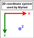
Such a setting can be obtained thanks to (with Erlang conventions):

gl:matrixMode(?GL_PROJECTION),
gl:loadIdentity(),

% Like glu:ortho2D/4:
gl:ortho(_Left=0.0, _Right=float(CanvasWidth),
  _Bottom=float(CanvasHeight), _Top=0.0, _Near=-1.0, _Far=1.0)

In this case, the viewport can be addressed like a usual (2D) framebuffer (like provided by any classical 2D backend such as SDL) obeying the coordinate system just described: if the width of the OpenGL canvas is 800 pixels and its height is 600 pixels, then its top-left on-screen corner is (0,0) and its bottom-right one is (799,599), and any pixel-level operation can be directly performed there "as usual". One may refer, in Myriad, to gui_opengl_2D_test.erl for a full example thereof, in which line-based letters are drawn to demonstrate these conventions.

Each time the OpenGL canvas is resized, this projection matrix has to be updated, with the same procedure, yet based on the new dimensions.

Another option - still with axes respecting the Myriad 2D conventions - is to operate this time based on normalised, definition-independent coordinates (see NDC), ranging in [0.0, 1.0], like in:

gl:matrixMode(?GL_PROJECTION),
gl:loadIdentity(),

gl:ortho(_Left=0.0, _Right=1.0, _Bottom=1.0, _Top=0.0, _Near=-1.0, _Far=1.0)

Using "stable", device-independent floats - instead of integers directly accounting for pixels - is generally more convenient. For example a resizing of the viewport will then not require an update of the projection matrix. One may refer to gui_opengl_minimal_test.erl for a full example thereof.

Referentials In 3D

We will rely here as well on the Myriad conventions, this time for 3D (not taking specifically time into account here, which anyway cannot be shown properly there):
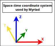
These are thus Z-up conventions (the Z axis being vertical and designating altitudes), like modelling software such as Blender.

Note that perhaps the most popular convention is different, it is Y-up, for which X is horizontal, Y is up and Z is depth (hence Z-buffer) - this axis pointing then to the user.

A Tree of Referentials

In the general case, either in 2D or (more often of interest here) in 3D, a given scene (a model) is made of a set of elements (e.g. the model of a street may comprise a car, two bikes, a few people) that will have to be rendered from a given viewpoint (e.g. a window on the second floor of a given building) onto the (flat) user screen (with suitable clipping, perspective division and projection on the viewport). Let's start from the intended result and unwind the process.

The rendering objective requires to have ultimately one's scene transformed as a whole in eye coordinates (to obtain coordinates along the aforementioned 2D screen referential, along the X and Y axes - the Z one serving to sort out depth, as per our 2D conventions).

For that, a prerequisite is to have the target scene correctly composed, with all its elements defined in the same, scene-global, space, in their respective position and orientation (then only the viewpoint, i.e. the virtual camera, can take into account the scene as a whole, to transform it ultimately to eye coordinates).

As each individual type of model (e.g. a bike model) is natively defined in an abstract, local referential (an orthonormal basis) of its own, each actual model instance (e.g. the first bike, the second bike) has to be specifically placed in the referential of the overall scene. This placement is either directly defined in that target space (e.g. bike A is at this absolute position and orientation in the scene global referential) or relatively to a series of parent referentials (e.g. this character rides bike B - and thus is defined relatively to it, knowing that for example the bike is placed relatively to the car, and that the car itself is placed relatively to the scene).

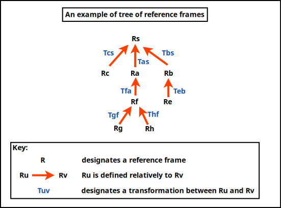
So in the general case, referentials are nested (recursively defined relatively to their parent) and form a tree [6] whose root corresponds to the (possibly absolute) referential of the overall scene, like in:

[6]

This is actually named a scene graph rather than a scene tree, as if we consider the leaves of that "tree" to contain actual geometries (e.g. of an abstract bike), as soon as a given geometry is instantiated more than once (e.g. if having 2 of such bikes in the scene), this geometry will have multiple parents and thus the corresponding scene will be a graph.

As for us, we consider referential trees (no geometry involved) - a given 3D object being possibly associated to (1) a referential and (2) a geometry (independently). This is as expressive, and most probably clearer.

A series of model transformations has thus to be operated in order to express all models in the scene referential:

(local referential of model Rh) -> (parent referential Rf) -> (parent referential Ra) -> (scene referential Rs)

For example the hand of a character may be defined in \(R_h\), itself defined relatively to its associated forearm in \(R_f\) up to the overall referential \(R_a\) of that character, defined relatively to the referential of the whole scene, \(R_s\). This referential may have no explicit parent defined, meaning implicitly that it is defined in the canonical, global, "world" referential.

Once the model is expressed as a whole in the scene-global referential, the next transformations have to be conducted : view and projection. The view transformation involves at least an extra referential, the one of the camera in charge of the rendering, which is \(R_c\), possibly defined relatively to \(R_s\) (or any other referential).

So a geometry (e.g. a part of the hand, defined in \(R_f\)) has to be transformed upward in the referential tree in order to be expressed in the common, "global" scene referential \(R_s\), before being transformed last in the camera one, \(R_c\).

In practice, all these operations can be done thanks to the multiplication of homogeneous 4x4 matrices, each able to express any combination of rotations, scalings/reflections/shearings, translations [7], which thus include the transformation of one referential into another. Their product can be computed once, and then applying a vector (e.g. corresponding to a vertex) to the resulting matrix allows to perform in one go the full composition thereof, encoding all model-view transformations (and even the projection) as well.

[7]In practice the recommended order of the operations are: scaling, then rotation, then translation, otherwise they will become coupled and would interfere negatively (e.g. a translation vector would be scaled as well).

Noting \(P_{a{\rightarrow}b}\) the transition matrix transforming a vector \(\vec{V_a}\) expressed in \(R_a\) into its representation \(\vec{V_b}\) in \(R_b\), we have:

\begin{equation*} \vec{V_b} = P_{a{\rightarrow}b}.\vec{V_a} \end{equation*}

Thus, to express the geometry of said hand (natively defined in \(R_h\)) in camera space (hence in \(R_c\)), the following composition of referential changes [8] shall be applied:

\begin{equation*} P_{h{\rightarrow}c} = P_{s{\rightarrow}c}.P_{a{\rightarrow}s}.P_{f{\rightarrow}a}.P_{h{\rightarrow}f}. \end{equation*}
[8]Thus transformation matrices, knowing that the product of such matrices is in turn a transformation matrix.

So a whole series of transformations can be done by applying a single matrix - whose coordinates are determined now.

Computing Transition Matrices

For that, let's consider an homogeneous 4x4 matrix is in the form of:

\begin{equation*} M = \begin{bmatrix} r_{11} & r_{12} & r_{13} & t_1 \\ r_{21} & r_{22} & r_{23} & t_2 \\ r_{31} & r_{32} & r_{33} & t_3 \\ 0 & 0 & 0 & 1 \\ \end{bmatrix} \end{equation*}

It can be interpreted as a matrix comprising two blocks of interest, \(R\) and \(\vec{T}\):

\begin{equation*} M = P_{1\rightarrow2} = \begin{bmatrix} R & \vec{T} \\ 0 & 1 \\ \end{bmatrix} \end{equation*}

with:

  • \(\matrix{R}\), which accounts for a 3D rotation submatrix:
\begin{equation*} R = \begin{bmatrix} r_{11} & r_{12} & r_{13} \\ r_{21} & r_{22} & r_{23} \\ r_{31} & r_{32} & r_{33} \\ \end{bmatrix} \end{equation*}
  • \(\vec{T}\), which accounts for a 3D translation vector:

\(\vec{T} = \begin{bmatrix} t1 \\ t2 \\ t3 \end{bmatrix}\)

Applying a (4x4 homogeneous) point \(P = \begin{Bmatrix} x \\ y \\ z \\ 1 \end{Bmatrix}\) to \(M\) yields \(P' = M.P\) where \(P'\) corresponds to \(P\) once it has been (1) rotated by \(\matrix{R}\) and then (2) translated by \(\vec{T}\) (the order matters).

Let's consider now:
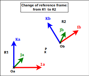
  • two referentials (defined as orthonormal bases), \(R_1\) and \(R_2\); \(R_2\) may for example be defined relatively to \(R_1\); for a given point or vector \(U\), \(U_1\) will designate its coordinates in \(R_1\), and \(U_2\) its coordinates in \(R_2\)
  • \(P_{2\rightarrow1}\) the (homogeneous 4x4) transition matrix from \(R_2\) to \(R_1\), specified first by blocks then by coordinates as:
\begin{equation*} P_{2\rightarrow1} = \begin{bmatrix} R & \vec{T} \\ 0 & 1 \\ \end{bmatrix} \end{equation*}
\begin{equation*} = \begin{bmatrix} r_{11} & r_{12} & r_{13} & t_1 \\ r_{21} & r_{22} & r_{23} & t_2 \\ r_{31} & r_{32} & r_{33} & t_3 \\ 0 & 0 & 0 & 1 \\ \end{bmatrix} \end{equation*}
  • any (4D) point \(P\), whose coordinates are \(P_1\) in \(R_1\), and \(P_2\) in \(R_2\)

The objective is to determine \(P_{2\rightarrow1}\), i.e. \(R\) and \(\vec{T}\).

By definition of a transition matrix, for any point \(P\), we have: \(P_1 = P_{2\rightarrow1}.P_2 \qquad (1)\)

Let's study \(P_{2\rightarrow1}\) by first choosing a point \(P\) equal to the origin of \(R_2\) (shown as Ob in the figure).

By design, in homogeneous coordinates, \(P_2 = Ob_2 = \begin{Bmatrix} 0 \\ 0 \\ 0 \\ 1 \end{Bmatrix}\), and applying it on \((1)\) gives us: \(P_1 = Ob_1 = \begin{Bmatrix} t1 \\ t2 \\ t3 \\ 1 \end{Bmatrix}\).

So if \(Ob_1 = \begin{Bmatrix} XOb_1 \\ YOb_1 \\ ZOb_1 \\ 1 \end{Bmatrix}\), we have: \(\vec{T} = \vec{T_{2\rightarrow1}} = \begin{bmatrix} XOb_1 \\ YOb_1 \\ ZOb_1 \end{bmatrix}\).

Let's now determine the \(r_{xy}\) coordinates.

Let \(R_{2\rightarrow1}\) be the (3x3) rotation matrix transforming any vector expressed in \(R_2\) in its representation in \(R_1\): for any (3D) vector \(\vec{V}\), we have \(\vec{V_1} = R_{2\rightarrow1}.\vec{V_2} \qquad (2)\)

(we are dealing with vectors, not points, hence the origins are not involved here).

By choosing \(\vec{V}\) equal to the \(\vec{Ib}\) (abscissa) axis of \(R_2\) (shown as Ib in the figure), we have \(\vec{Ib_1} = R_{2\rightarrow1}.\vec{Ib_2}\)

Knowing that by design \(\vec{Ib_2} = \begin{bmatrix} 1 \\ 0 \\ 0 \end{bmatrix}\), \((2)\) gives us:

\begin{equation*} \vec{Ib_1} = \begin{bmatrix} r_{11} \\ r_{21} \\ r_{31} \end{bmatrix} = \begin{bmatrix} XIb_{1} \\ YIb_{1} \\ ZIb_{1} \end{bmatrix} \end{equation*}

So the first column of the \(R\) matrix is \(\vec{Ib_1}\) , i.e. the first axis of \(R_2\) as expressed in \(R_1\).

Using in the same way the two other axes of \(R_2\) (shown as Jb and Kb in the figure), we see that:

\begin{equation*} R = R_{2\rightarrow1} \end{equation*}
\begin{equation*} = \begin{bmatrix} XIb_{1} & XJb_{1} & XKb_{1} \\ YIb_{1} & YJb_{1} & YKb_{1} \\ ZIb_{1} & ZJb_{1} & ZKb_{1} \\ \end{bmatrix} \end{equation*}

So the transition matrix from \(R_2\) to \(R_1\) is:

\begin{equation*} P_{2\rightarrow1} = \begin{bmatrix} R_{2\rightarrow1} & \vec{T_{2\rightarrow1}} \\ 0 & 1 \\ \end{bmatrix} = \begin{bmatrix} XIb_1 & XJb_1 & XKb_1 & XOb_1 \\ YIb_1 & YJb_1 & YKb_1 & YOb_1 \\ ZIb_1 & ZJb_1 & ZKb_1 & ZOb_1 \\ 0 & 0 & 0 & 1 \\ \end{bmatrix} \end{equation*}

where:

  • \(R_{2\rightarrow1}\) is the 3x3 rotation matrix converting vectors of \(R_2\) in \(R_1\), i.e. whose columns are the axes of \(R_2\) expressed in \(R_1\)
  • \(\vec{T_{2\rightarrow1}} = Ob_1\) is the 3D vector of the coordinates of the origin of \(R_2\) as expressed in \(R_1\)

This also corresponds to a matrix obtained by describing the \(R_2\) referential in \(R_1\), by listing first the three (4D) vector axes of \(R_2\) then its (4D) origin, i.e. \(P_{2\rightarrow1} = \begin{bmatrix} \vec{Ib_1} && \vec{Jb_1} && \vec{Kb_1} && Ob_1 \end{bmatrix}\).

Often, transformations have to be used both ways, like in the case of a scene-to-camera transformation; as a consequence, transition matrices may have to be inversed, knowing that \((P_{2\rightarrow1})^{-1} = P_{1\rightarrow2}\) (since by definition \(P_{2\rightarrow1}.P_{1\rightarrow2} = Id\)).

An option to determine \(P_{1\rightarrow2}\) from \(P_{2\rightarrow1}\) could be to compute its inverse directly, as \(P_{1\rightarrow2} = (P_{2\rightarrow1})^{-1}\), yet \(P_{1\rightarrow2}\) may be determined in a simpler manner.

Indeed, for a given point \(P\), whose representation is \(P_1\) in \(R_1\) and \(P_2\) in \(R_2\), we obtain \(P_1 = P_{2\rightarrow1}.P_2\) by - through the way (4x4) matrices are multiplied - first applying a (3x3) rotation \(Rot_3\) to \(P_2\) and then a (3D) translation \(T_r\): \(P_1 = Rot_3.P_2 + T_r\) (in 3D; thus leaving out any fourth homogeneous coordinate); therefore \(P_2 = (Rot_3)^{-1}.(P_1 - T_r)\). Knowing that the inverse of an orthogonal matrix is its transpose, and that rotation matrices are orthogonal, \((Rot_3)^{-1} = (Rot_3)^\top\), and thus \(P_2 = (Rot_3)^\top.(P_1 - T_r) = (Rot_3)^\top.P_1 - (Rot_3)^\top.T_r\).

So if:

\begin{equation*} P_{2\rightarrow1} = \begin{bmatrix} R_{2\rightarrow1} & \vec{T_{2\rightarrow1}} \\ 0 & 1 \\ \end{bmatrix} \end{equation*}

then:

\begin{equation*} P_{1\rightarrow2} = \begin{bmatrix} (R_{2\rightarrow1})^\top & -(R_{2\rightarrow1})^\top.\vec{T_{2\rightarrow1}} \\ 0 & 1 \\ \end{bmatrix} = \begin{bmatrix} XIb_1 & YIb_1 & ZIb_1 & -(XIb_1.XOb_1 + YIb_1.YOb_1 + ZIb_1.ZOb_1) \\ XJb_1 & YJb_1 & ZJb_1 & -(XJb_1.XOb_1 + YJb_1.YOb_1 + ZJb_1.ZOb_1) \\ XKb_1 & YKb_1 & ZKb_1 & -(XKb_1.XOb_1 + YKb_1.YOb_1 + ZKb_1.ZOb_1) \\ 0 & 0 & 0 & 1 \\ \end{bmatrix} \end{equation*}

Note

Therefore, in a nutshell, the transition matrix from a referential \(R_\alpha\) to a referential \(R_\beta\) is:

\begin{equation*} P_{\alpha\rightarrow\beta} = \begin{bmatrix} Rot_{\alpha\rightarrow\beta} & \vec{Tr_{\alpha\rightarrow\beta}} \\ 0 & 1 \\ \end{bmatrix} = \begin{bmatrix} XIb_\beta & XJb_\beta & XKb_\beta & XOb_\beta \\ YIb_\beta & YJb_\beta & YKb_\beta & YOb_\beta \\ ZIb_\beta & ZJb_\beta & ZKb_\beta & ZOb_\beta \\ 0 & 0 & 0 & 1 \\ \end{bmatrix} \end{equation*}

where:

  • \(Rot_{\alpha\rightarrow\beta}\) is the 3x3 rotation matrix converting vectors of \(R_\alpha\) in \(R_\beta\), i.e. whose columns are the axes of \(R_\alpha\) expressed in \(R_\beta\)
  • \(\vec{Tr_{\alpha\rightarrow\beta}} = Ob_\beta\) is the 3D vector of the coordinates of the origin of \(R_\alpha\) as expressed in \(R_\beta\)

This also corresponds to a matrix obtained by describing the \(R_\alpha\) referential in \(R_\beta\), by listing first the three (4D) vector axes of \(R_\alpha\) then its (4D) origin, i.e. \(P_{\alpha\rightarrow\beta} = \begin{bmatrix} \vec{Ib_\beta} && \vec{Jb_\beta} && \vec{Kb_\beta} && Ob_\beta \end{bmatrix}\).

Its reciprocal (inverse transformation) is then:

\begin{equation*} P_{\beta\rightarrow\alpha} = \begin{bmatrix} (Rot_{\alpha\rightarrow\beta})^\top & -(Rot_{\alpha\rightarrow\beta})^\top.\vec{Tr_{\alpha\rightarrow\beta}} \\ 0 & 1 \\ \end{bmatrix} = \begin{bmatrix} XIb_\beta & YIb_\beta & ZIb_\beta & -(XIb_\beta.XOb_\beta + YIb_\beta.YOb_\beta + ZIb_\beta.ZOb_\beta) \\ XJb_\beta & YJb_\beta & ZJb_\beta & -(XJb_\beta.XOb_\beta + YJb_\beta.YOb_\beta + ZJb_\beta.ZOb_\beta) \\ XKb_\beta & YKb_\beta & ZKb_\beta & -(XKb_\beta.XOb_\beta + YKb_\beta.YOb_\beta + ZKb_\beta.ZOb_\beta) \\ 0 & 0 & 0 & 1 \\ \end{bmatrix} \end{equation*}

As a result, from the definition of a tree of referentials, we are able to compute the transition matrix transforming the representation of a vector expressed in any of them to its representation in any of the other referentials.

A special case of interest is, for the sake of rendering, to transform, through that tree, a local referential in which a geometry is defined into the one of the camera, defining where it is positioned and aimed [9]; in OpenGL parlance, this corresponds to the model-view matrix (for "modelling and viewing transformations") that we designate here as \(M_{mv}\) and which corresponds to \(P_{local{\rightarrow}camera}\).

[9]gluLookAt can define such a viewing transformation matrix, when given (1) the position of the camera, (2) a point at which it shall look, and (3) a vector specifying its up direction (i.e. where is the upward direction for the camera - as otherwise all directions orthogonal to its line of sight defined by (1) and (2) could be chosen).

Taking into account the last rendering step, the projection (comprising clipping, projection division and viewport transformation), which can be implemented as well thanks to a 4x4 (non-invertible) matrix designated here as \(M_p\), we see that a single combined overall matrix \(M_o = M_p.M_{mv}\) is sufficient [10] to convey in one go all the transformations that shall be applied to a given geometry for its rendering.

[10]In practice, for more flexibility, in older (pre-shader) OpenGL the management of the viewport, of the projection and of the model-view transformations was done separately (for example, respectively, with: glViewport, glMatrixMode(GL_MODELVIEW) and glMatrixMode(GL_PROJECTION); so, in compatibility mode, there is a matrix stack corresponding to GL_MODELVIEW and another one to GL_PROJECTION.

Main Matrices

These matrices account for the main processing steps of a rendering.

Three types of referentials can be considered:

  • world referential: the absolute, overall referential where 3D scenes are to be assembled
  • local referential: the referential in which a given model is defined (generally placed at its origin)
  • camera referential: a referential where a camera is at the origin, looking down on the negative Z axis

The clip space can also be considered; this is the post-projection space, where the view frustum is transformed into a cube, centered in the origin, and going from -1 to 1 in every axis.

The transformations between referentials can be represented by 4×4 transition matrices:

  • model matrix (\(M_M\)): to transform from local to world referential
  • view matrix (\(M_V\)): to transform from world to camera referential
  • projection matrix (\(M_P\)): to transform from camera referential to clip space

Finally, two composite matrices are especially useful (note the aforementioned reverse multiplication order) and are typically passed through uniform variables in shaders:

  • ModelView: \(M_{MV} = M_V.M_M\)
  • ModelViewProj: \(M_{MVP} = M_P.M_{MV} = M_P.M_V.M_M\)

Shaders

They are covered in-depth in the Khronos wiki.

A Programmable Pipeline

Shaders are the basic rendering building blocks of applications using modern OpenGL (e.g. 3.x/4.0 versions).

Such an application will indeed program its own shaders, instead of calling functions like glBegin()/glEnd() as it was done with OpenGL 1.x-2.x and its fixed-pipeline immediate mode.

This mode of operation, albeit more complex, offers more control and enables increased performances.

Parallelism in the Pipeline

The key is to write programs that can be executed in a Single Instruction, Multiple Data (SIMD) setting, in order to take advantage of the vectorization typically supported by GPUs.

A goal is to avoid conditional branching based on values that may differ from a shader invocation to another (see this explanation).

If having to take into account two dynamically-uniform (i.e. non-statically predictable, yet having the same value for every shader invocation within that group) branches performing simple computations, it is likely that the compiler will generate code evaluating both expressions, until dropping the result of the one finally not happening.

Six Types of GLSL Shaders

Shaders are written in the GLSL language, i.e. the OpenGL Shading Language.

They are portions of C-like code that can be inserted in the rendering pipeline implemented by the OpenGL driver of a GPU card. Six different kinds of shaders can be defined, depending on the processing step that they implement and on their purpose: vertex, tessellation for control or for evaluation, geometry, fragment or compute shaders.

Except this last type (compute shader), all types are mostly dedicated to rendering. If wanting to perform on one's GPU more general-purpose processing, OpenCL shall be preferred to GLSL.

Each shader is to receive data to process that is appropriate to its type; for example each vertex shader instance will receive a vertex (multiple of such instances will process each their own vertex in parallel) whereas each fragment shader will operate on data specific to a pixel.

So shader instances will vary in terms of role (e.g. in charge of the processing of a vertex or a fragment), data types (input and output ones) and multiplicities (number of instances). Indeed, if considering a triangle whose vertices are each pure green, red or blue, only 3 vertices will be processed by the vertex shaders, whereas all the numerous pixels of the triangle will be the result of the evaluation of as many fragment shaders, each input of which is computed by interpolating the attributes of said 3 vertices - which ultimately results in a smooth gradient over the whole triangle.

Runtime Build

Shaders are compiled at (application) runtime [11] (to target exactly the actual hardware), then linked and attached to a separate program running on the GPU. This is fairly low-level, black-box direct programming, in sharp contrast with the reliance on APIs that used to be the norm with OpenGL 1.x.

[11]So each shader is built each time the application is started, and the operation may fail (e.g. with 0(40) : error C1503: undefined variable "foobar").

Yet offline compilers exist as well, as well as debuggers (like the NVIDIA NsightShader Debugger).

Implementing a Shader

A shader is quite similar to a C program, yet based on a specific, core language that enables the definition of relevant data types and functions.

Data types are usually based on elementary types (float, double, bool, int and uint), and composed in larger structures, like {vec,mat}{2,3,4}, mat2x3, arrays and structures, possibly const; see this page for further details.

Similarly, control flow statements and (non-recursive) functions can be defined; every shader must have a main function, and can define other auxiliary functions as well, in a way similar to a C program. Function parameters may have the in (which is the default), out or inout qualifiers specified. Additionally a function may return a result, thanks to return.

So, regarding output, for example a fragment shader must return the color that it computed: out vec3 my_color; declares this; and the shader code may be as simple as returning a constant color in all cases, like in:

#version 330 core
out vec3 my_color;

void main()
{
   // Same color returned for all fragments:
   my_color = vec3(0.05, 0.2, 0.67);
}

Communicating with Shaders

Of course the application must have a way of supplying information to its shaders (the other way round does not really happen, except for compute shaders), and a given shader must be able to pass information to (only) any next shader in the pipeline.

Two options exist for shaders to have inputs and outputs, from/to the CPU and/or other shaders:

  • basically each shader is fed with a stream of vertices [12] with associated data, named vertex attributes; these attributes are either user-defined or built-in (each type of shader having its own set of built-in input attributes)
  • global, read-only data can also be defined, as uniform variables
[12]Then the user-defined primitives, applied later in the pipeline, will allow OpenGL to interpret such a series of vertices in terms of a sequence of triangles, or points, or lines, etc.

These communication options are discussed more in-depth next.

Vertex Attributes

Defining Attributes

A vertex attribute, whether user-defined or built-in, may store any kind of data - notably positions, texture coordinates and normals.

Either a given attribute is a single, standalone one (then a unique value will be read and will apply to all vertices), or is per-vertex, in which case it is read from a buffer, each element of it being bound accordingly when its associated vertex is processed by the shader. Such arrays are either used in-order, or according to any indices defined (then themselves defined thanks to an array as well) [13].

[13]This is the preferred method, as it prevents vertex duplication, and allows to process each of them once: there is a vertex cache that stores the outputs of the last processed vertices, so that if a vertex is mentioned multiple times (e.g. being included in a triangle fan or strip), the corresponding output may be directly re-used (provided it is still in the cache) instead of having to be computed again.

Said differently, for each attribute used by a shader, either a single value or an array thereof must be specified.

Referencing Attributes

In order that attributes can be defined in a place (program or shader) and referenced later by at least one shader, they must be matched:

  • by (attribute) name: then they must bear exactly the same name in the main program and in the shader(s) using them, knowing that any name beginning with gl_ is reserved
  • or by (attribute) location: their common location is specified, and a per-shader variable name is associated - which is more flexible
  • or by block, like for the uniform variables, discussed below

In the two last cases, the layout of variables must match on either side (for example in the main program and a given shader); for instance, with "layout(location = 0) in vec3 input_vertex;" in its code, a vertex shader will expect a (single) vector of 3 (floating-point) coordinates (vec3) to be found at index 0 (location = 0) as input (in); the application will need to specify a corresponding Vertex Buffer Object (VBO) for that.

So that they can be fetched for a given vertex, attributes have to be appropriately located in buffers. For each attribute, either the developer defines, prior to linking, a specific location (as an index starting at zero) with glBindAttribLocation, or he lets OpenGL choose it, and queries it afterwards, with glGetAttribLocation; refer to this page for further details.

If a given program is linked with two shaders, a vertex one and a fragment one, the former one will probably have to pass its outputs as inputs of the latter one; this requires as many variables defined on either side, with relevant out/in specifications, and a matching name and type; for example the vertex shader may declare out vec3 my_color; whereas the fragment shader will declare in vec3 my_color;.

Providing Attribute Data : VAO and VBO

Vertex data is provided thanks to a (single current) Vertex Array Object (VAO).

A VAO references (rather than storing directly) the format of the vertex data, as well as the buffers (VBOs, see below) holding that data.

A vertex attribute is identified by a number (in [0;GL_MAX_VERTEX_ATTRIBS-1]), and by default is accessed as a single value (as opposed to as an array).

A Vertex Buffer Object (VBO) is a data array, typically referenced by a VAO. A VBO defines its internal structure and where the corresponding data can be found.

So, in practice, each homogeneous chunk of data (vertices, normals, colors) to be sent from the CPU-space to the GPU-space (hence from the client side to the server one) is stored in an array corresponding to a Vertex Buffer Object (VBO), itself referenced by a Vertex Array Object (VAO). A VAO may gather vertex data and colour data in separate VBOs, and store them on the graphics card for any later use (as opposed to streaming vertices through to the graphics card when they become needed). A VAO is only meant to hold one (VBO) array of vertices, each other VBO being used then for per-vertex attributes.

Uniform Variables are Read-Only and Global

Instead of relying on attributes, an alternate way of passing information, provided that it may change relatively infrequently, is to use uniform variables, which behave, for a shader and in the course of a draw call, as read-only, constant global variables for all vertices (hence their uniform naming). Any shader can access every uniform variable (they are global), as long as it declares that variable, and these variables hold as long as they are not reset or updated.

Examples of uniform variables could be the position of a light, transformation matrices, fog settings, variables such as gravity and speed, etc.

Uniform variables may be defined individually, or be grouped in named blocks, for a more effective data setup (to share uniform variables between programs) and transfer from the application to the shader (setting multiple values at once).

Uniform variables are declared at the program-level (as opposed to a per-vertex level) thanks to:

  • the uniform qualifier on the shader-side, like in uniform mat4 MyMatrix;
  • a glGetUniformLocation call on the application-side, to create a location associated to a variable name (e.g. my_matrix) in a shader, and to associate it to a given value, like, in C:
mat4 some_matrix = [...];

GLuint location = glGetUniformLocation(programId, "my_matrix");

if (location >= 0)
{
   // Defining a single matrix (1), not to transpose (GL_FALSE):
   glUniformMatrix4fv(location, 1, GL_FALSE, &some_matrix[0][0]);
   [...]

Individual variables may be used as uniform, as well as arrays and structs.

From the point of view of a shader, these named input variables may be initialised when declared, but then are read-only; otherwise the application may choose to set them.

Built-in Variables are Defined by Each Shader Type

Finally, depending on the type of a shader, some predefined, built-in variables ("intrinsic attributes") may be set; they are specified here.

For example, for a vertex shader, following output variables are predefined:

  • vec4 gl_Position corresponding to the clip-space (homogeneous) position of the output vertex
  • float gl_PointSize
  • float gl_ClipDistance[]

Troubleshooting Shaders

Once a shader builds correctly, it may misbehave at runtime.

One may refer to the "Debugging shader output" section of this page.

Examples of Shaders

See the ones of Wings3D (in GLSL "1.2" apparently, presumably for maximum backward compatibility; note that some elements, with the *.cl extension, are OpenCL ones), or these ones.

Managing Spatial Transformations

Modern OpenGL (and GLU) implementations basically dropped the direct matrix support (the so-called immediate mode does not exist anymore, except in a compatibility context). So no more calls to glTranslate, glRotate, glLoadIdentity or gluPerspective shall be done; now the application has to compute such matrices (for model, view, texture, normal, projection, etc.) by itself (on the CPU), and the result thereof can be send on the GPU, as input to its GLSL shaders (typically thanks to uniform variables).

For that, applications may use dedicated, separate libraries, such as, in C/C++, GLM, i.e. OpenGL Mathematics [14] (Myriad's linear support aims to provide, in Erlang, a relevant subset of these operations - albeit admittedly in a simplified form).

[14]GLM is a free software header-only, template-based C++ library. See its manual and for example its implementation of 4x4 float-based matrices (and their corresponding type definition). Note that, as GLM is targeted at OpenGL, by default it adopts column-major internal conventions, leading to a somehow unfamiliar mode of operation.

The matrices that correspond to the transformations to be applied are then typically shared with the shaders thanks to uniform variables.

This is especially the case for the vertex shader, in charge of transforming coordinates expressed in a local referential into screen coordinates.

More precisely, the modeling (object-space to absolute, world-space), viewing (world-space to camera-space) and projection transformation (camera-space to clip-space) are applied in the vertex shader, whereas the final perspective division and the viewport transformation are applied in the fixed-function stage after the vertex shader.

So a vertex shader is usually given two 4x4 homogeneous, uniform matrices:

  • a modelview matrix, combining modeling and viewing, to transform object-space to camera-space in one go
  • a projection matrix

More Advanced Topics

Shadows

Determining the shadow of an arbitrary object on an arbitrary plane (representing typically the ground - or other objects) from an arbitrary light source (possibly at infinity) corresponds to performing a specific projection. For that, a relevant 4x4 (based on homogeneous coordinates) matrix (singular, i.e. non-invertible matrix) can be defined.

This matrix can be multiplied with the top of the model-view matrix stack, before drawing the object of interest in the shadow color (a shade of black generally).

Refer to this page for more information.

Reference GLSL Compiler

As always, different compilers (corresponding to different brands of graphical cards) will not implement exactly the same way the (OpenGL, here) specification; and a shader may work correctly on one type of card and not on another.

Testing shader code with the OpenGL / OpenGL ES Reference Compiler, a.k.a. glslang (installed on Arch Linux thanks to pacman -Sy glslang, to be run as glslangValidator) may report interesting information.

See the OpenGL GLSL reference compiler section of this page for more information.

Sources of Information

The reference pages for the various versions of OpenGL are available on the Khronos official OpenGL Registry.

Two very well-written books, strongly recommended, that are still relevant for 3D graphics despite their old age (circa 1996; for OpenGL 1.1):

More modern tutorials (applying to OpenGL 3.3 and later) are:

Other elements of interest:

Operating System Support for 3D

Benefiting from a proper 2D/3D hardware acceleration on GNU/Linux is unfortunately not always straightforward, and sometimes brittle.

The very first step is to update's one's video drivers to their latest, official stable version according to your OS/distribution of choice (even if it implies using closed-source binaries...) and to check that they are in use (probably reboot then).

Testing

First, one may check whether such acceleration is already available by running, from the command-line and as the current, non-priviledged user, the glxinfo executable (to be obtained on Arch Linux thanks to the mesa-utils package), and hope to see, among the many displayed lines, direct rendering: Yes.

One may also run our display-opengl-information.sh script to report relevant information.

A final validation might be to run the glxgears executable (still obtained through the mesa-utils package), and to ensure that a window appears, showing three gears properly rotating.

Troubleshooting

If it is not the case (no direct rendering, or a GLX error being returned - typically involving any X Error of failed request:  BadValue for a X_GLXCreateNewContext), one should investigate one's configuration (with lspci | grep VGA, lsmod, etc.), update one's video driver on par with the current kernel, sacrifice a chicken, reboot, etc.

If using a NVidia graphic card, consider reading this Arch Linux wiki page first.

In our case, relevant installations could be done with pacman -Sy nvidia nvidia-utils but required a reboot.

Despite package dependencies and a not-so-successful attempt of using DKMS in order to link kernel updates with graphic controller updates, too often a proper 3D support was lost, either from the boot or afterwards. Refer to our software update section for hints in order to secure the durable use of proper drivers.

Minor Topics

Camera Navigation Conventions

Multiple tools introduced conventions in order to navigate, with mouse and keyboard, in a 3D world.

We prefer the way Blender manages the observer viewpoint (current camera), as described here; notably, supposing a three-button mouse with a scrollwheel:

  • orbit the view around the currently selected object (or Tumble) by holding the middle button down and moving the mouse
  • pan (moving the view up, down, left and right) by holding down Shift and the middle button, and moving the mouse
  • zoom in/out with the scrollwheel; a variation of it, Dolly, can be obtained by holding down Ctrl and the middle button, and moving the mouse